|
ROSCHEN
|
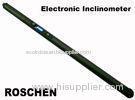
Multi Shot Electronic Inclinometer for Oil Drilling / Exploration Drilling
| Place of Origin: | Zhejiang, China (Mainland) |
|
|
|
| Add to My Favorites | |
| HiSupplier Escrow |
Product Detail
Multi Shot Electronic Inclinometer for Oil Drilling / Exploration Drilling
&
Multi Shot Electronic Inclinometer for Oil Drilling / Exploration Drilling
Product description:
1. Intuitive operator interface.
Users do not need manual can prompt completion of all the features provided by the probe according to the probe panel, simple operation, intuitive and fast.
2. Embedded powerful direct reading.
Without ground instrument with the probe can be done alone display of the parameters, settings and printing. Eliminating the need for ground instruments, greatly save the time of measurement.
3. Assured smart reminder.
The intelligent reminder feature real-time detection of various states of the probe in the work, and to detect the fault and display. For the user to ensure that the instrument is normal to go down before.
4. Acceleration sensor and magnetometer. Global advanced MEMS process.
Advantage of MEMS technology, the probe can provide high-precision measurements in harsh working environments, and other low power MEMS process the probe has a longer working time. Work environment and low power consumption are the traditional mechanical sensors can not match.
5. Unique momentary power failure from the restore function.
Completely avoided in the process of the instrument downhole, and instantaneous power interruption caused by a shock, vibration and cause the failure of the measurement. Probe to restore the original state of the work.
6. To meet a variety of practices.
Meet hanging measured with different underground protection assembly voted measured, the job requires a self-floating way.
7. Measuring range and accuracy.
|
Project |
Measuring range |
Measurement Accuracy |
Restrictions |
|
Borehole Deviation |
0180° |
±0.1° |
/ |
|
Magnetic Bearing |
0360° |
±1° |
Borehole deviation≥6° |
|
High-Side Tool Face |
0360° |
±0.5° |
Borehole deviation≥6° |
|
Magnetic Tool Face |
0360° |
±1° |
Borehole deviation≤8° |
8. Single multi-point integrated design.
Roschen multi-point probe by the probe panel, the choice of a single multi-point work. Actually equivalent to the user to purchase two of the probe. Single point probe measurement in drilling when drilling is completed with multi-point probe tube pulled out the well-rail. Save user investment.
9. Technical indicators:
Temperature: -40~125 (with insulation protection assembly, the maximum operating temperature of 250);
Vibration: frequency 10 ~ 100Hz, vibration acceleration ≤4.5g, half-sine;
Shock: Shock ≤2000g, 0.5ms;
Operating voltage: DC6V ~ DC8V;
Working current: DC5V power supply conditions, standby operating current ≤ 30mA acquisition operating current ≤150mA;
Operating temperature: -40 ~ 125;
Impact resistance: 2000g, 0.5ms;
Vibration resistance: 10g, 20 ~ 100Hz;
Dynamic performance:
the acceleration of the vibration conditions 3g, frequency of 20Hz, borehole deviation measurements with static measurements, borehole deviation error ≤0.2°;
Delay time range:
1 to 99 minutes, the minimum delay of 1 minute;
Interval range:
1 to 99 seconds, minimum interval of 1 second (only applicable to multi-way);
Maximum sampling points:
3600 points. (Only applicable to multi-way);
Continuous working time:
more than 20 hours (only applicable to multi-way).
Multi-shot Inclinometer:
The user may use ‘←’or‘→’ on the panel to choose ‘S’(Single Shot) or ‘M’(Multi-Shot) when the two buttons flickering. Press ‘ Confirm’ for confirmation. The tube will be ready for a working mode when the choice for single shot or multi-shot is made, which will be confirmed by the stop of flickering of the button ‘S’ or ‘M’.
For re-select a working mode, the removal of battery barrel is required.
1. Connection of the external protection component
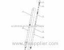
Under the mode of directional measuring, tie the steel rope on the Socket head and bolt the Rubber protector on the Brass connector. Then connect the following parts according to the Figure 4-4, rope socket head, circumrotate hanger, radial buffer, brass connector and external protecting barrel. Install the lead seal on the guide shoe.
Under the mode of non-directional measuring, connect the bottom buffer, radial buffer, multi-buffer, extended bar and brass connector according to the figure 4-5. Bolt the rubber protector on the brass connector tightly. Then connect the external protecting barrel. Remember to tighten each connecting part with rubber pipe spanner. Put the steel rope through the hole of the rocket head and tie up. Bolt the rubber protector on the brass connector tightly. According to the figure 4-5, connect the rope socket head, circumrotate hanger, radial buffer and brass connector.
2. Assembling
In directional measuring
Hang the T-head of the probe-tube on the directional buffer connector. Then put them into the external protecting barrel.
Tighten the directional buffer connector and install the lead seal on the guide shoe.
In non-directional measuring
Hang the battery barrel on the rubber hanger and hang the T-head on the rubber protector. Put them into the external protecting barrel and bolt the brass connector. Tighten each connecting part with rubber pipe spanner.
3. Data Reading
See 4.3 step 5 self-floating mode.
Cautions:
Ø The voltage of battery must be higher than 4.8V before the inclinometer is put into the well.
Ø In directional measuring, high side correcting must be performed. If the directional part of the external protector is re-assembled before measuring, the gravity high side must be corrected.
Ø The buffer ring must be assembled with the probe-tube.
Ø In suspending measuring, the descending speed must be lower than 3m/s. When the instrument closing the measuring point, the descending speed should be lower than 1m/s.


